Open Trench Installation

Uploading
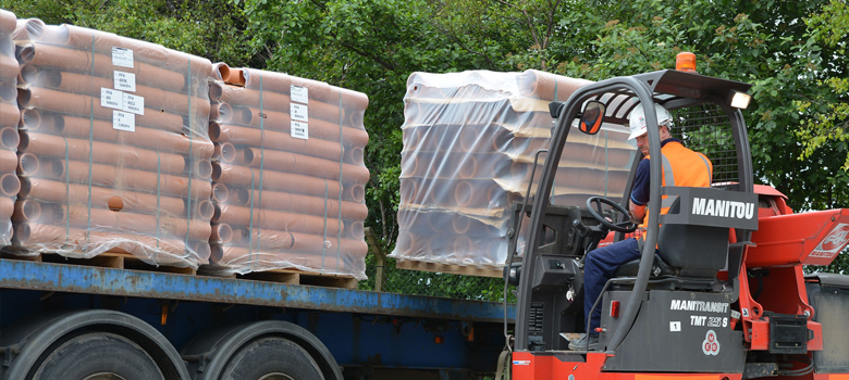
Access to site must be over a hard road capable of supporting a fully laden vehicle. The delivery vehicle must be parked on firm, flat ground. Pipes are typically delivered to site in packs weighing between 1 and 2 tonnes. Fittings are usually supplied in crates or are shrunk wrapped. Any loose fittings should be removed by hand from the delivery vehicle before other goods are unloaded.

There is usually a choice between:
1 Use of foldfork self-loading vehicle
The prime-mover is detached from the trailer-load and is operated as a fork-lift to unload the packs and crates. For this purpose, approx. 10 metres of firm ground are required alongside the trailer.
If conditions allow, packs may be placed around the site in order to reduce subsequent handling.
2 Using site equipment to unload (this is the responsibility of the Contractor.)
The packs and crates can be offloaded by fork-lift, or by suitable crane, or other machine using a sling.
3 Hand offloading by site personnel
Check that the pack is stable and that the pipes and packing woods are undamaged before cutting the straps and manually unloading.
Stacking
1 Pipes delivered in packs
Set the pack down on a firm and level surface.
2 Storage of loose pipes
Rest the bottom row of pipes on battens to keep them clear of the ground and stake the end pipes in order to prevent movement of the stack.
3 Sleeve couplings and lubricant
Store indoors in a clean area, away from sunlight. Extremes of temperature must be avoided. Winter conditions, in particular, can affect the ability to make a joint if items have been left outdoors.
Trench Excavation
There should be at least 150mm width of trench on each side of the pipe barrel, in order to provide sufficient space for jointing and proper compaction of the bedding and fill materials.
It is not good practice to excavate a trench too far in advance of pipe-laying.
Do not exceed the specified maximum trench width without prior approval of the supervising authority, because the trench width affects the loading on the pipeline.
When trenches are battered, the maximum allowable trench width must not be exceeded below a point 300mm above the crown of the pipes.
Always provide adequate support to the trenches, for the protection of workmen and to prevent damage to adjacent property. The attention of all site personnel should be drawn to the requirements of the Health and Safety Executive. Ref. BS8000: Workmanship on Building Sites Pt. 14: Below Ground Drainage. CIRIA R97 Trenching Practice.
Pipe Laying
Line & Level
The correct pipeline alignment and gradient are indicated by laser equipment or by using a taut string and sight rails.
Pipe manufacturing tolerances need to be taken into account when assessing line and level. For guidance in setting out see CIRIA A Manual of Setting Out Procedures.
Class D, N, F, B & S Beddings
Compact the bed to the correct level. Commence pipelaying from the lower end of the line. Lay pipes with their couplings facing upstream. Take care to achieve continuous bedding support. If it is necessary to raise a pipe to the correct level, the pipe should be removed and additional bedding material compacted along the full barrel length – prior to relaying.
Concrete Beddings
Blind the trench bottom with a 50mm thick layer of concrete. Place concrete support blocks on the trench blinding, immediately downstream of each pipe coupling position. Place a compressible board on top of each block and lay the pipes on these. Fine adjustments of the pipe levels can be achieved by using wedges fixed between the pipe barrels and the blocks. To maintain flexibility at joints, fix compressible boards immediately upstream of couplings at the specified intervals along the length of the pipeline. Brace the pipes to prevent any tendency to float when the concrete surround is placed and vibrated.
Inspect & clean pipes & jointing components
Before laying, check the pipes and fittings to ensure that they have not suffered damage. Make sure that the pipe ends, jointing components and lubricant are clean from grit, before attempting to make joints.
Testing
Testing the pipeline for water tightness
When laying clay pipes, it may be convenient to check that all is in order by applying interim air tests to progressive lengths of pipework as work proceeds.
Once a pipeline has been laid an air or water test may be carried out in accordance with BS EN1610, as detailed below.
Air Test:
- Fix air-tight stoppers at the ends of the pipeline, after checking that they are clean and well-fitting. Connect a manometer to one of the stoppers.
- Blow or pump air into the pipeline until a pressure slightly more than the required air test pressure is indicated on the manometer. After allowing 5 minutes for the temperature to stablise, adjust to the required pressure and commence the test.
- (a) If the measured drop is less than the allowable drop then the test is passed (see table). Note: The test pressure LA is the same as that previously used in the UK except that the test period is increased for sizes above DN225, as shown.
Test period in minutes
| Test Method | Test press mbar (kPa) |
Allowable drop mbar (kPa) |
Test period in minutes | ||||
| DN100 | DN200 | DN300 | DN400 | DN600 | |||
| LA | 10 (1) | 2.5 (0.25) | 5 | 5 | 7 | 10 | 14 |
(b) If the measured drop exceeds the allowable loss, carefully check the testing apparatus and stoppers and examine the pipes and joints for leakage. If a defect is discovered, remedy it and re-test.
If this test does not reveal a defect, apply a water test.
The above standards do not regard an air test alone as sufficient grounds for rejection and it is recommended that a water test should be applied in the event of apparent failure to meet the air test. An apparent failure of air test can be due to causes other than defects in the pipework; for example, changes in ambient temperature.
Water Test:
- At the upstream end of the pipework to be tested, add a 90o bend and sufficient vertical pipes to provide the required head of water. BS EN1610 requires a minimum 1.0m (10kPa) head of water at the high end with a maximum of 5m (50kPa) at the lower end. Both heads above the pipe crown. In cases of very steep gradients, it may be necessary to test the pipe stages, in order to comply with these limitations.
- Tighten stoppers at the lower end of the pipeline and at open branches, after checking that they are clean and well-fitting.
- Strut the ends of the pipeline and the 90o bend to prevent movement and then fill the line with water.
- Inspect the pipeline for any obvious leaks and remedy any defects. There will be an initial fall of the water level due to absorption and the displacement of trapped air.
- After at least one hour, top up to the maximum test head, a longer period may be allowed in extremely dry conditions. The loss of water over a period of 30 minutes should then be measured by adding water from a measuring vessel at regular intervals of 10 minutes and noting the quantity required to maintain the original water level. The test is accepted if the water added does not exceed 0.15l/m2 of internal wetted area over a 30 minute period, for pipelines. Higher limits are set for pipelines including manholes and inspection chambers.
Further information
See BS EN1610 and the Clay Pipe Development Association Ltd booklets Specification, Design and Construction and Testing of Drains & Sewers (Water & Air Tests).
Backfilling:
Any selected or granular fill must be carefully hand-compacted in layers not exceeding 150mm to complete the pipeline surround. Place and compact this fill equally on both sides of the pipeline to prevent displacement.
Slice with a spade around the barrels to form a cradle for the pipes. This work is important, as the pipeline derives some of its strength from a properly constructed bedding.
The trench must be backfilled to at least 300mm above the crown of the pipes before any power-ramming takes place. Backfill should then be well-compacted in layers not exceeding 300mm.
As backfilling proceeds withdraw timber and trench sheeting in stages to avoid disturbing the pipeline or the creation of voids within the bedding and surround.
Site Traffic:
Site traffic should not pass over buried pipelines before backfilling has been completed and the final surface constructed.
Overloading by unavoidable site traffic can be prevented by bridging the trench with steel plates, timber sleepers or other temporary protection.
Useful videos to help you install your clay pipes:

