Structural Design
Clay pipes not only have a reduced bedding requirement as compared to flexible pipe materials, but bedding design may incorporate the use of recycled aggregates arising from e.g. construction demolition waste. The papers below provide further detail.
Research Paper 815 – click here
Your Partner in Materials and Technology Use of Recycled Aggregates as Clay Pipe Bedding. J.D.Barnes and C.Beardmore, (1999)
BRE Digest 433 – click here
Recycled Aggregates
CPDA Technical Note Number 9 – click here
Laying Vitrified Clay Pipes on Recycled Material
The load bearing capacity of any pipeline is dependent upon the inherent strength of the pipes and fittings together with the support provided by the bedding in which the pipe is laid.
Before specifying drainage, the designer must choose between the two alternative forms of pipe systems. These are:
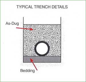 Rigid Pipes with Flexible Joints
For building drainage these are usually vitrified clay with sleeve joints. These pipes, having very high inherent strength, require little or no bedding material.
Clay pipes and fittings can often be laid on the natural trench bottom or with a regulating layer of “as dug” material or inexpensive gravel bed. Such a system can be expected to give a satisfactory performance throughout the design life of the building.
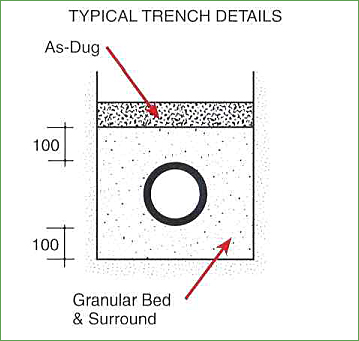 Flexible Plastic Pipes
In building drainage, PVCu is the most common material. These pipes have little inherent strength and are dependent on substantial bedding for support. The minimum such requirement is usually 100mm granular bed and pipe surround.
The quality and proper placing of the bedding material is of paramount importance and this system therefore relies heavily upon the competence of the site operatives and on good site supervision. The incorrect laying of flexible pipes could result in flattening and ultimate failure.
Structural Strength
The figures for Crushing Strength and Bending Moment Resistance (B.M.R) in BS EN 295 Part 1 have been established after extensive research into the loads imposed on buried vitrified clay pipelines. The requirements for B.M.R have been set sufficiently high to ensure that pipes conforming to these, and used in a properly constructed pipeline, will not fail in bending before they reach their design crushing load. Testing for B.M.R is only applicable to pipes up to and including DN225 and with normal lengths equal to or greater than 1.1m.
With pipes less than 1.1m in length research has shown that the bending moments developed are insufficient to be of concern to the designer.
Clay pipes, when used with the appropriate bedding, have the capacity to withstand the full range of trench backfill and surcharge loads that are encountered in all but the most extreme site conditions.
Strength
The Crushing Strength and Bending Moment Resistance of vitrified clay pipes are detailed in Manufacturers Product Information Leaflets.
Trench Beddings
Depths of cover between which clay pipes conforming to BS EN 295 can be laid in any width of trench.
DN |
Min. Crushing Strength a b |
Bedding Class |
Bedding Factor |
Depth of Cover to Crown of Pipe | |
| Main Traffic Roads a b |
Fields and Gardens a b |
||||
100 |
34 40 | D or N F B or S |
1.1 1.9 2.5 |
0.4 – 7.1 0.4 – 8.4 0.4 – 10.0+ 0.4 – 10.0+ 0.4 – 10.0+ 0.4 – 10.0+ |
0.4 – 7.3 0.4 – 8.7 0.4 – 10.0+ 0.4 – 10.0+ 0.4 – 10.0+ 0.4 – 10.0+ |
150 |
34 40 | D or N F B or S |
1.1 1.9 2.5 |
0.6 – 4.5 0.6 – 5.6 0.6 – 8.5 0.6 – 10.0+ 0.6 – 10.0+ 0.6 – 10.0+ |
0.6 – 5.0 0.6 – 5.9 0.6 – 8.7 0.6 – 10.0+ 0.6 – 10.0+ 0.6 – 10.0+ |
225 |
36 45 | D or N F B or S |
1.1 1.9 2.5 |
0.9 – 2.6 0.9 – 3.9 0.6 – 5.9 0.6 – 7.6 0.6 – 8.0 0.6 – 10.0+ |
0.6 – 3.5 0.6 – 4.4 0.6 – 6.2 0.6 – 7.8 0.6 – 8.2 0.6 – 10.0+ |
300 |
48 72 | D or N F B or S |
1.1 1.9 2.5 |
0.8 – 2.7 0.6 – 3.5 0.6 – 6.0 0.6 – 9.4 0.6 – 8.1 0.6 – 10.0+ |
0.6 – 3.5 0.6 – 5.4 0.6 – 6.3 0.6 – 9.5 0.6 – 8.3 0.6 – 10.0+ |
375 |
45 60 | D or N F B or S |
1.1 1.9 2.5 |
– 0.8 – 3.0 0.6 – 4.5 0.6 – 6.4 0.6 – 6.3 0.6 – 8.7 |
0.6 – 2.7 0.6 – 3.8 0.6 – 5.0 0.6 – 6.7 0.6 – 6.6 0.6 – 8.8 |
400 |
64 80 | D or N F B or S |
1.1 1.9 2.5 |
0.8 – 2.9 0.6 – 4.2 0.6 – 6.3 0.6 – 8.0 0.6 – 8.5 0.6 – 10.0+ |
0.6 – 3.7 0.6 – 4.7 0.6 – 6.6 0.6 – 8.2 0.6 – 8.7 0.6 – 10.0+ |
450 |
54 72 | D or N F B or S |
1.1 1.9 2.5 |
– 0.8 – 3.0 0.6 – 4.5 0.6 – 6.5 0.6 – 6.3 0.6 – 8.7 |
0.6 – 2.7 0.6 – 3.8 0.6 – 5.0 0.6 – 6.7 0.6 – 6.6 0.6 – 8.9 |
500 |
60 80 | D or N F B or S |
1.1 1.9 2.5 |
– 0.8 – 3.0 0.6 – 4.5 0.6 – 6.4 0.6 – 6.3 0.6 – 8.7 |
0.6 – 2.7 0.6 – 3.8 0.6 – 5.0 0.6 – 6.7 0.6 – 6.6 0.6 – 8.8 |
Other crushing strengths may be available. For further details consult manufacturers’ sales department.
Bedding Classes
The bedding factors indicated below refer to the cross-sectional design of pipes. It assumes that uniform support is achieved along the entire length of the pipeline.
The bedding factors incorporate the revisions to Class F, B and S beddings as detailed in WRC Information & Guidance Notes 4-11-02 and are specific to the use of vitrified clay pipes.
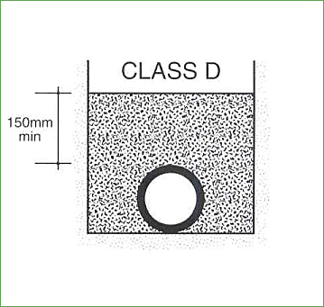 CLASS D – PIPES LAID ON A TRENCH BOTTOM (BEDDING FACTOR 1.1)
Appropriate when the trench formation is:
- Capable of being trimmed with a spade
- Is not puddled when walked upon
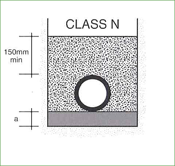 CLASS N – PIPES LAID ON A GRANULAR BED (BEDDING FACTOR 1.1)
When it is impractical to trim the trench bottom, a continuous bed of granular material of one of the following is required:
- As dug material with a compaction factor of up to 0.3 as W.I.S 4-08-02
- All – in aggregate 20mm (may be recycled concrete)
- Granular material to Tables B15-B17 of App B to BS EN1610
- Sand (coarse, medium or fine) conforming to BS882 Table 4
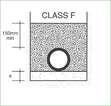 CLASS F – PIPES LAID ON A BED OF SINGLE SIZE OR GRADED MATERIAL (BEDDING FACTOR 1.9)
Appropriate where the depth of cover over the pipe requires a higher bedding factor:
- 20mm single size or 20 to 5mm graded granular material to conform to Tables B15-B17 of App B to BS EN1610
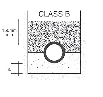 CLASS B – PIPES LAID ON GRANULAR MATERIAL (BEDDING FACTOR 2.5)
Appropriate where the highest bedding factor is required to resist the applied loads on the pipeline.
- 20mm single size or 20 to 5mm graded granular material to conform to Tables B15-B17 of App B to BS EN1610
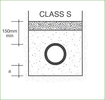 CLASS S – PIPES LAID IN GRANULAR MATERIAL (BEDDING FACTOR 2.5)
An alternative to Class B when the excavated material is unsuitable as the initial backfill.
- 20mm single size or 20 to 5mm graded granular material to conform to Tables B15-B17 of App B BS EN1610
Minimum dimension ‘a’
| Socketed pipes | Plain End Pipes | |
| Uniform Soils | 100mm | 50mm |
| Rock or Mixed soils | 200mm | 150mm |

Recycled aggregates may be used for all bedding classes provided that they conform to the particle size requirements of Table B15-B17 of App B to BS EN1610 and have a compaction fraction of 0.3 or less.
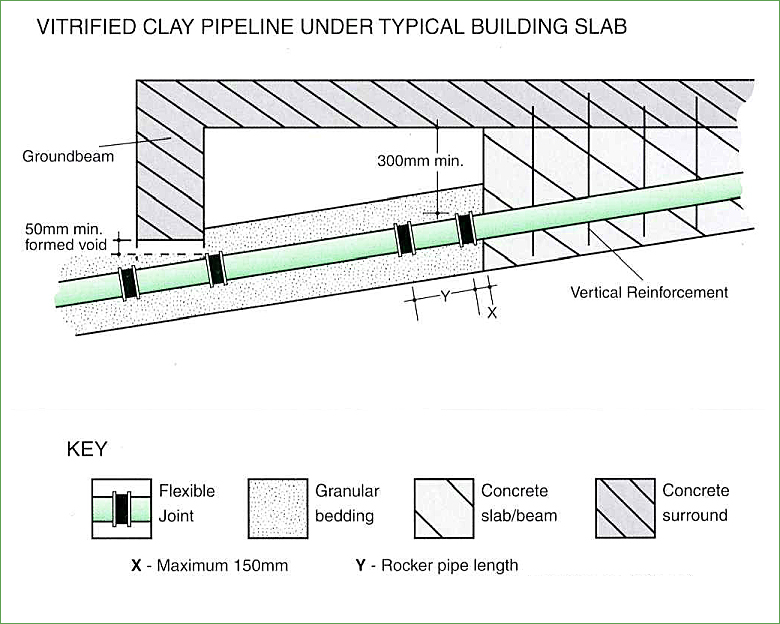
Pipelines under structures or buildings
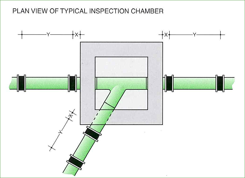
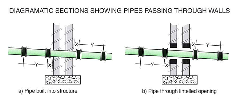
Allowance must be made for possible differential settlement in pipelines passing
a) through structures or
b) under buildings by the inclusion of additional flexible joints as illustrated. Further details are contained in the C.P.D.A. booklet “Technical Notes for Vitrified Clay Pipes”.
a) through structures
b) under buildings
Concrete Beddings
When a line of flexibily jointed pipes is bedded, haunched or surrounded in concrete, flexibility can be maintained along its length by employing 18mm thick compressible boards at pipe joints. These should extend the full height and width of the concrete and should occur at maximum intervals of 5m along the length of the pipeline. The boards should be positioned against the upstream end of pipe sockets or sleeves as shown below.

