LAYOUTS
The members of CPDA produce publications incorporating suggested drainage layouts – please contact CPDA Members for further details. Generic drawings are set out below.
Soil Waste Connections
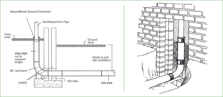
Soil and vent pipe
Connection of soil, ventilating and combined soil and ventilation pipes. (Including optional Rodding Eye Point).
Notes
- The above ground drainage system may be connected to the clay system with an appropriate connector available to suit from 75mm to 150mm uPVC or cast-iron pipes.
- Where the building exceeds two storeys, 2 No. 45° bends should be used in place of the Rest Bend shown.
- The drain may be aligned in any direction by rotating the Rest Bend about its vertical axis.
- If the pipe is used for ventilation only, the diameter may be 75mm instead of 100mm.
Rainwater connections
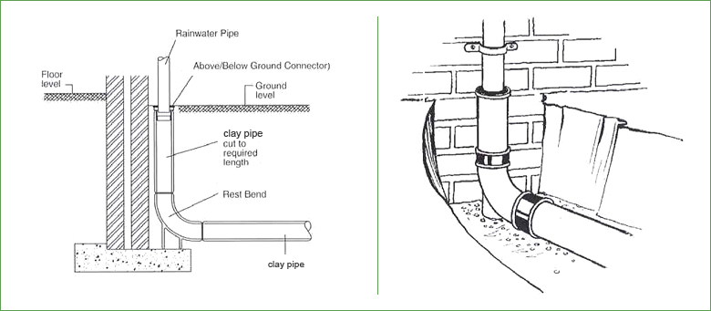
Direct Connection
Notes
A 90° Bend may be used in place of the Rest Bend. This provides a more economical layout but is more difficult to construct.
Universal Gully
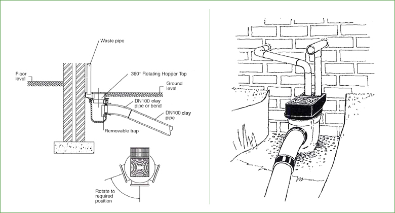
Notes
- The hopper top can be rotated about its vertical axis to align the drain as required.
- The Gully provides a rodding facility at the head of a run.
- The drain can be rodded by removing the grate and trap.
Rainwater Gully
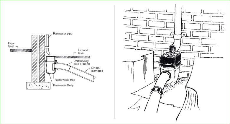
Notes
Rainwater Shoe or access pipe receiving discharge over a gully grid does comply with the requirements of Approved Document H of Building Regulations but may not be accepted in all areas.
Access & Inspection Layouts
Plastic Inspection Chamber – 100mm inlets/outlets
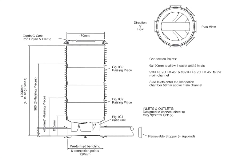

Purpose
Unit is designed for use to a depth of up to 1200mm (BS EN752:2008).
Materials
Inspection Chamber – Injection moulded, polypropylene see illustration.
Stoppers – Polypropylene stoppers.
Plastic Inspection Chamber – DN100/150 inlet – DN150 outlet
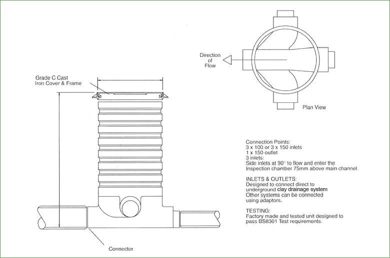
Plastic Inspection Chambers – General Installation Details
Bedding
Position the Chamber on a prepared base of selected ‘as-dug’ or granular material (min 100mm depth), or of concrete (min 150mm, see BS EN1610 Clause 5.3.3.1 and annex B gives details of granular material suitability), to achieve a common line and level with the main pipeline. Where concrete is used, the Chamber should be placed while the concrete is still wet, to ensure satisfactory bedding of the Chamber.
Incoming connections should then be made, jointing the clay pipes or fittings directly into the Chamber. Use lubricant, as when making a normal pipe joint. All unused inlet connections should remain blanked off, using the stoppers supplied. If selected ‘as-dug’ or granular material is used, this should then be tamped between the pipe connections and, as far as possible, hand packed and compacted underneath the Chamber base contours, in order to ensure uniform support.
Surround
Selected ‘as-dug’ or granular material should be tamped around the Chamber in 250mm layers up to surface level.
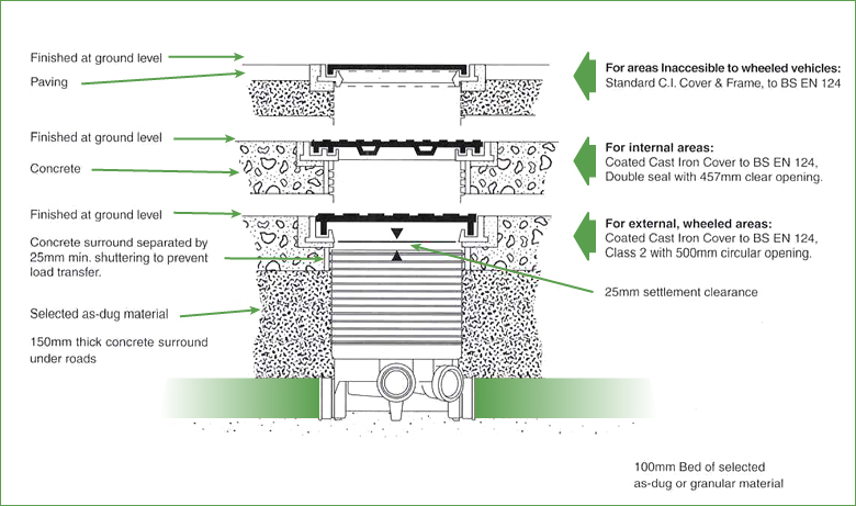
For additional protection against damage from traffic, a concrete collar may be placed around the top of the Chamber. Under roads, the Chamber should be surrounded with 150mm of concrete.
Fixing Cover
The standard Cast Iron Circular Cover and Frame is designed to fit directly over the top of the Chamber.
It is advisable to place the Cover and Frame on the unit PRIOR to back filling, in order to keep out waste material.
Rodding Points
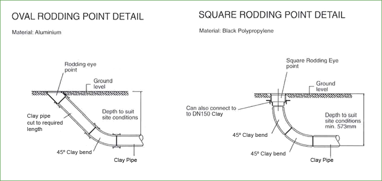
Purpose – To facilitate one-way rodding using normally acceptable manual rodding techniques.
Connections – Pipework from the Rodding Eye should connect to the drain at an angle not greater than 45°. This permits easy rodding in one direction only. The pipework should be of the same diameter as the drains they serve.
Note: Rodding Eye Points may also be incorporated into Hopper/Low Back Trap arrangements to make the arrangement roddable.
Traditional Manhole Construction
Where chambers are required at depths greater than 1.2 metres, these may be constructed in brickwork or in concrete sections. The open channel work in the base of the manhole can be constructed using Channel pipes and fittings.
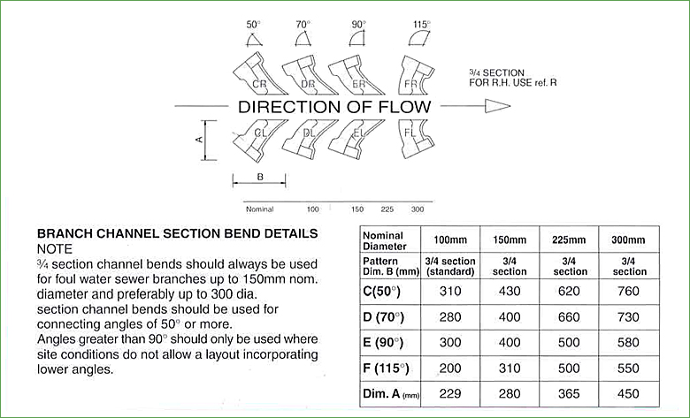
A wide range of 100mm, 150mm, 225mm, 300mm diameter vitrified clay Channel pipes, bends and junctions are available. Also 100mm and 150mm diameter ¾ section Channel bends. Acute Channel bends turn a drain into the direction of the main flow, but can prevent adequate access up the incoming drain. In foul systems, therefore Channel bends in excess of 90° should not generally be used.
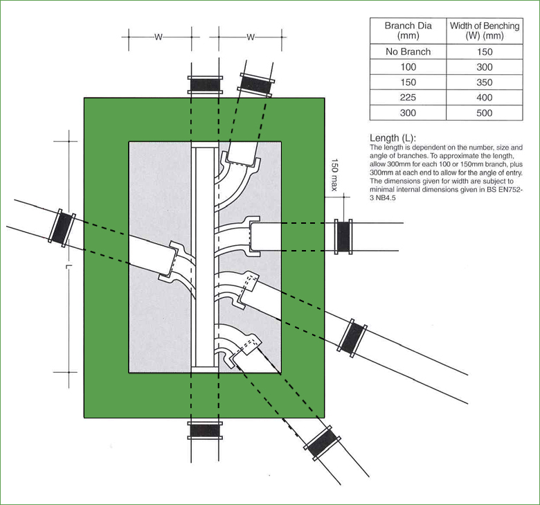 Side connections may connect to the main branch by either a pre-formed junction or by section bends discharging over the top of the main channel. The latter is preferred by the Regulations as it results in no interruption of main channel flow.
All Channel items are supplied for use with cement mortar joints and can be used with all types of underground drainage materials. Each pipe entering or leaving a manhole should have a flexible joint within 150mm of the manhole wall. In poor ground, further flexibility can be provided by installing a further short length of pipe (a rocker pipe), approx. 600mm long.
Design Layout
Back-drop Manholes
Back-drop manholes are often required where the invert level of the incoming drain is significantly higher than that of the manhole.
In the case of small sewers (about DN300 or less) BS EN752:2008 (see national annex NB4.7) suggests that a ramp may be used if the invert level difference is less than 1.8m. In the past, backdrop manholes were constructed on drains and sewers to avoid using steep gradients. Recent research has shown that steep gradients do not cause increased erosion or the deposition of solids and as a result backdrops are less frequently used in this situation.


