Design of Clay Drainage Systems

The section on Structural Design covers matters such as pipe strengths, depths and bedding requirements.
The section on Hydraulic Design covers matters such as pipe sizing and flow rates.
Design Layout
Clay pipes and fittings which are produced to BS EN295: part 1: 2013 when installed in accordance with the enclosed installation instructions satisfy all the requirements of The Building Regulations 2010.
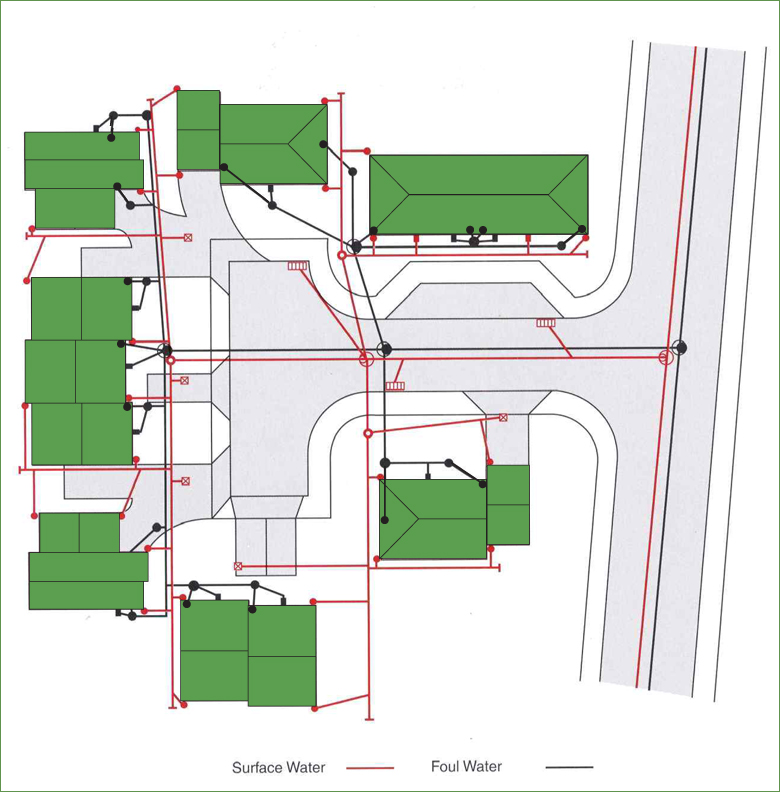
Typical Site Plan
The design and layout of a clay drainage system should be in accordance with the Guidance Documents listed in the Legislation and Standards section. The layout should be kept as simple as possible and the routes selected should make full use of the natural slopes of the ground or any adjustments thereto, so as to achieve the required gradients with minimum excavation. Changes of direction and gradient should be minimised.

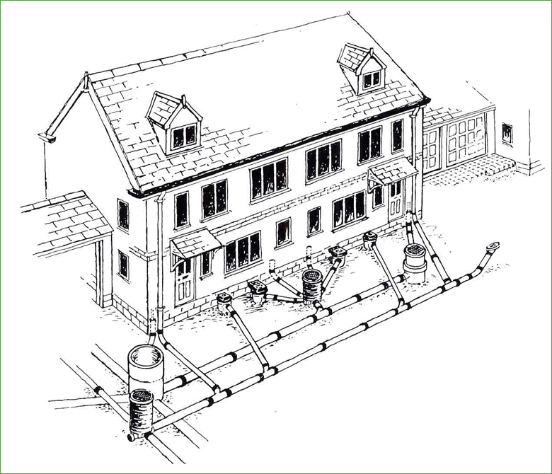
Typical Building Drainage Design and Layout

 Provision of access to drains
As the bulk of drainage is buried it is necessary to provide access to the system to allow rodding and the removal of debris. Both BS EN 752:2008 Table NA.20 and the Building Regulations Document H details recommendations for the siting and sizing of access fittings.
- Every drain length should be accessible for maintenance and rodding without the need to enter the building
- Access should be provided at the head of a drain run
- Access should be provided on a branch drain within 12m of every junction with a main pipe, unless there is an inspection chamber at the junction
- Access should be provided at changes of direction, pipe size or gradient
- Every soil and vent and WC pan connection must discharge into an inspection chamber
- Access should be provided at suitable locations to aid the testing of pipe runs
- Each drain length must be roddable from at least one point
- Bends of no more than 45° may be used outside inspection chambers
The maximum distance between access points
Distance to |
From access point |
From junction or branch |
From inspection chamber |
From manhole |
|
1 |
2 |
||||
| m | m | m | m | m | |
| Start of external drain | 12 | 12 | – | 22 | 45 |
| Rodding eye | 22 | 22 | 22 | 45 | 45 |
| Access fitting (1) min. 150mm x 100mm or 150mmØ | – | – | 12 | 22 | 22 |
| Access fitting (2) min. 225mm x 100mm | – | – | 22 | 45 | 45 |
| Inspection chamber – Shallow | 22 | 45 | 22 | 45 | 45 |
| Manhole and deep inspection chamber | – | – | – | 45 | 90* |
* Up to 200m for man-entry sized sewers (see BS EN752-3 NB2.2)
The minimum dimensions for rodding eyes, access fittings, inspection chambers and manholes
| Type of access | Depth to invert (M) | Min. internal dimensions (mm) | Min. nominal cover size (mm) | Remarks | ||
| Rectangular | Circular | Rectangular | Circular | |||
| Access fitting | 0.6 or less except where situated in a chamber | (1) 150 x 100(2) 225 x 100 | 150 225 |
150 x 100 225 x 100 |
150 same size as access fitting | The depth restriction is imposed because of the limited access afforded by these items and is based on the ability to manipulate a stopper at arm’s length from the surface |
| Inspection Chamber (shallow) | 0.6 or less | 225 x 100 | 190Ø for drains up to DN150 | – | Min 90 | The depth restriction is imposed as for the access fitting |
| 1.2 or less | 450 x 450 | 450 | Min 430 x 430 |
Min 430 | Restricted to inspection and remotely operated equipment. No personnel entry | |
| Manhole or Inspection chambers (deep) | Greater than 1.2 |
450 x 450 | 450 | 300 x 300 Max access allowed | 350 Max access allowed | Restricted to inspection and remotely operated equipment. No personnel entry. Max size imposed to prevent personnel entry |
| Rodding Eye | Preferably same size as drain, but not less than 100Ø | – | – | |||
Other requirements
Gradient – Pipes should be laid to even gradients and any change in gradient should be combined with an access point.
Direction – Pipes should be laid in straight lines where practicable but may be laid to slight curves if these can be cleared of blockages.
Junctions – Where practicable connections should be to inspection chambers or manholes but connections to junctions are acceptable if access is provided to clear blockage. In all cases discharge to be in the direction of flow at the point of connection.
Bends – Bends should be positioned in or adjacent to terminal fittings, inspection chambers or manholes and at the foot of discharge stacks. Bends should have as large a radius as practicable.
Ventilation – The system should be ventilated at or near the head of each main drain to allow free passage of air throughout, the maximum length of any branch serving a single appliance being 6m and for a group appliances 12m.
Traps – Where appliances are not fitted with integral traps at the point of discharge a trap must be provided using either a trapped gully or low back trap. In addition a surface water pipe discharging into a combined system should be trapped.
Special precautions should also be taken to accommodate the effects of settlement where pipes run under or near a building, on piles or beams, in common trenches or in unstable ground. Precautions may also be necessary in situations involving surcharging of drains, or where control of rodents is a problem.
Terminal and Access Fittings
The diagrams above show suggested combinations of fittings for the connection of soil, waste and rainwater pipes to underground drainage systems.
The layouts will satisfy the majority of drainage requirements, as well as complying with Building Regulations. However if the suggested layouts are not suitable for a particular application, the CPDA members offer a wide range of other fittings to fully satisfy any drainage design.
